
I used Peter Stuge’s “ghetto” method to replace a PLCC bios chip with a socket on an asus m2a-2vm board. This board has excellent coreboot support.
The method basically consists of cutting off the legs of the PLCC chip as close to the package as possible, so as to minimize strain on the paths on the motherboard while cutting. After that, the legs can easily be de-soldered from the board, and it’s trivial to solder on a PLCC socket. Obviously you loose the PLCC chip in the process, but this method is a lot easier than removing the PLCC chip with a heat gun. It’s also safer for the surrounding components.
Here are some photos:
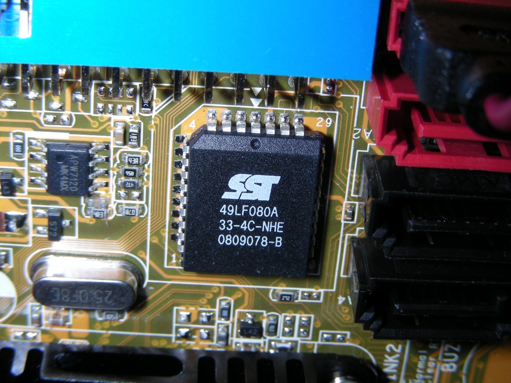
The chip prior to modification.
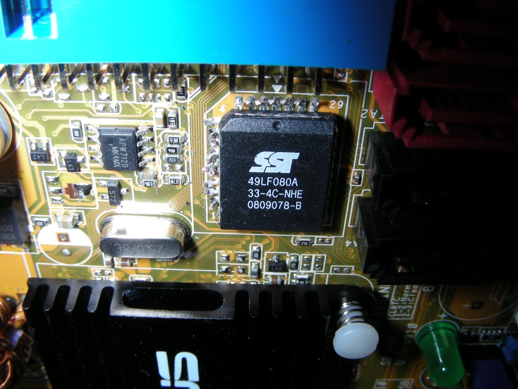
Legs cut off on two sides of the chip. It’s important to use the right cutter for this job – it needs to be able to cut very closely to the package of the chip. I used a Hakko CHP Ergonomic Micro Cutter, part number TR20M.
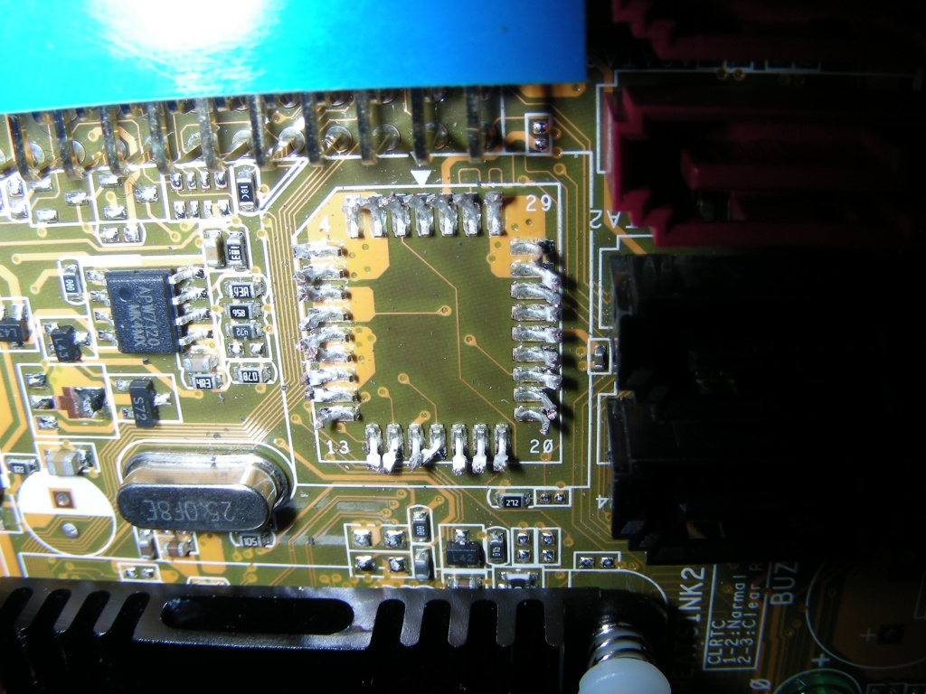
PLCC chip removed.
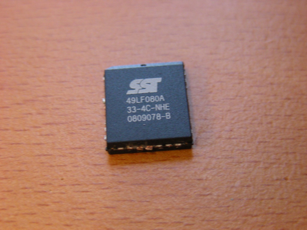
PLCC chip without legs.
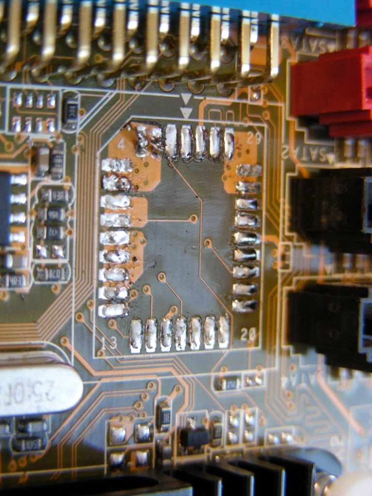
The legs have been de-soldered. If you look carefully near pins 1 and 2 on the top row, you’ll see I was foolish and used too much force and a too small soldering tip while de-soldering. I damaged the board. Luckily the pins involved are all on the same big pad, and everything still works.
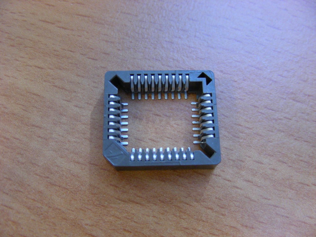
This is the socket prior to soldering. I had to remove the plastic ‘floor’ of the socket in the center to allow easy access to the pins for soldering. You can put that piece of plastic back in the socket after it has been soldered onto the board, even loose. It will prevent PLCC chips from being pushed too deep into the socket, where not all pins might make contact with the socket.
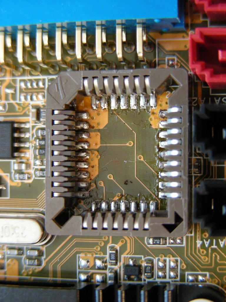
The PLCC socket, installed.
![[Play OGG]](/blog/wp-content/photos/play_ogg_small.png)